The price of 1 cubic meter of "factory" concrete is from 1600 to 3600 rubles (depending on the characteristics of the mixture and the impudence of the supplier), and pouring it into the manufactured formwork will cost 1000 rubles per 1 m 3 or more. And that is not all! It is worth adding here the development of soil, backfilling of sand, gravel, and even materials “lost” by guest workers.
Installation strip foundation do-it-yourself will save up to 140%, while doing it just like 2 + 2. The main problem on the way is reinforcement. Here, mistakes can be very costly, so it is necessary to consider the entire process in detail. Your attention step-by-step instruction formwork and rebar installation with visual aids and helpful tips.
Basic rules for reinforcing a strip foundation
Let's start with the main mistakes of beginners, the rules of SNiP and general recommendations that must be followed. Consider those that can significantly affect the quality of the foundation and the fate of your future building.
- To reinforce the strip foundation of a 1-2-storey house, rods of 10-24 mm are used. It is advisable to take the average value, a smaller diameter is unacceptable.
- Welded joints are prohibited, only knitting of reinforcement is allowed. Welding overheats the metal, reducing its tensile strength by 1.6-2.5 times in places of perpendicular fastening.
- If the soil has a uniform density around the entire perimeter, we use thinner reinforcement (10-14 mm). With a non-uniform density, the rods should be thick (16-24 mm).
- It is not recommended to use "smooth" fittings when reinforcing the foundation with your own hands. The adhesion of the material (adhesion to concrete) will be much less than that of corrugated rods, making calculations even more difficult. Smooth reinforcement is allowed for transverse joints - the load on them will be much less.
- Longitudinal reinforcement inside the foundation should be placed no closer than 5 centimeters from the formwork. The rule also applies to the base and top of the foundation. Otherwise, the foundation may crumble around the edges, and the reinforcement itself will rust.
- The distance between the crossbars can be from 25 to 45 centimeters, it is not desirable to violate this range in low-rise construction.
- The reinforcement of the corners of the strip foundation differs from the laying of the reinforcement along the trench, it is necessary to carry it out according to a special scheme (we will consider it later in the article).
- Longitudinal rods are laid every 40 centimeters of the height of the foundation. For example, with a height of 120 centimeters, it is necessary to lay 3 layers of longitudinal reinforcement
Master's advice: all data must comply with SNiP foundations 2.02.01-83 and 2.03.01-84, it would be better to read the requirements in detail before starting work. Do not rely on the "eye", all work must be performed in accordance with the instructions and standards.
Do-it-yourself formwork installation
A properly made frame for the foundation will not only save a lot of money on the purchase of concrete, but also greatly simplify the reinforcement process. If you already have it, you can skip this step and go straight to reinforcement, if not, then consider the step-by-step instructions.
STEP 1 : choice of material. With a low foundation height, it is quite easy to choose the material: plywood, wood, OSB-plates, DPV. The main requirement is the strength of the material. For high foundations (from 150 cm), only metal is used, since the concrete pressure will be significant and the tree can fail.
STEP 2: ground preparation. Let's say we have a trench that meets the standards, now it is necessary to compact the base. We pour a layer of sand 150 mm, fill it with water, then 4-5 centimeters of concrete to level the surface. Do not forget about communications, they must be made at the stage of formwork and reinforcement of the foundation of the house, we must not forget about the embedded pipes in the right places, otherwise you will have to work with a puncher for a long time and break the solidity of the foundation.
STEP 3: having a construction project, we install pegs along the perimeter of the trench exactly the width of the future foundation, they will hold the bottom of the formwork, put spacers at least 70% of the height of the structure (the spacer itself is 2 times more height foundation). It does not hurt to make 3-4 control rails per foundation width, by which it will be possible to measure width deviations.
Master's advice: it is necessary to drive nails from the inside of the formwork into spacers and pegs, so that later everything can be removed without problems. Otherwise, you will have to break wooden beams or cut off hats, since protruding nails are concreted. If the foundation is from 150 cm and above, it is recommended to tie the formwork with wire in a checkerboard pattern every 1 m.
The formwork should be as rigid as possible, the gaps between the structural elements should not exceed 0.3 cm, so that when the foundation is poured, the liquid mixture does not flow out, otherwise the strength of the foundation will decrease exponentially.
It must withstand solid loads and retain its shape after pouring cement, this is the only way to do it. monolithic foundation for a house that will last for decades.
Important: the inside of the formwork must be lubricated with technical oil or other petroleum products (working off is suitable) so that it can be more easily peeled off from concrete after it has hardened. You can use it many times.
Photos of strip foundation formwork
Formwork with spacers 
 Correct formwork
  Panel formwork
Installation of reinforcement around the entire perimeter of the strip foundation
The formwork is ready, now you can proceed to the most important process - reinforcing the foundation with your own hands. They use steel and fiberglass reinforcement, we will focus on the first option, since it will be much cheaper. We will need to purchase the following materials:
- longitudinal reinforcement 14-18 mm thick (average value, your project may be different);
- transverse and vertical rods with a diameter of 10-12 mm;
- knitting steel wire;
- good wire pliers or pliers (or very strong hands).
Important: it is necessary to fasten the reinforcement with knitting steel wire, since it has a low stretch coefficient and is strong enough. This will greatly simplify the assembly of the structure, but the wire does not affect the strength of the foundation, it only fixes the reinforcement before pouring the foundation.
STEP 1 : We make calculations and purchase materials. Calculating how much materials you need is very easy. Transverse rods are placed at a distance of about 30 centimeters (small errors are not terrible), longitudinal pair reinforcement every 40 centimeters in height (do not forget the first section), and vertical - after 60 cm. Divide the length of the wall by the number of crossbars and the number of "tiers" of longitudinal reinforcement . Consider the example of a foundation 10x10 meters and a height of 120 cm:
- 1000 cm: 30 cm = 33 (the number of transverse rods on 1 tier);
- 33 x 3 = 99 (number of cross bars per 1 side);
- 99 x 4 = 396 (all bars on 4 sides).
Now we multiply 396 by the width of the foundation (let it be 70 cm for us): 396 x 70 = 27720 cm. 277 meters of bars must be bought. We carry out similar calculations for longitudinal reinforcement:
- 1000 x 2 = 2000 (one tier);
- 2000 x 3 = 6000 (side);
- 6000 x 4 = 24000 cm (need to purchase 240 meters).
And, of course, vertical elements. We will put them on both sides of the foundation with a frequency through one transverse jumper, that is, after 60 cm:
- 2 x 17 = 34 (pieces per side);
- 34 x 4 \u003d 136 (pieces for the entire base);
- 136 x 120 cm = 16320 cm or 163 meters.
We substitute the parameters of your structure as an example and get the correct calculation of the elements for reinforcing the strip foundation of the house. Do not forget 5-8% for "every fireman".
STEP 2: Do you already have 5-6 cm of concrete at the bottom of the trench for leveling? Skip this step. If not, we fill up 15 cm of sand, then 5 cm of concrete, level everything, do not forget about communications and a place for them. If there is no desire to mess around, you can simply put a thick PVC film on the bottom. The main task of this step is to level the ground and retain some of the water that will appear after pouring the concrete.
STEP 3 : knitting reinforcement for a strip foundation. You can do it in a trench or nearby, if it is inconvenient to turn around there or the trench itself is too narrow according to the project. With a “remote” assembly, it will immediately be necessary to think about ways to lower the metal down so as not to damage the structure. Consider how to make the reinforcement of the foundation with your own hands:
- We start with the lower crossbars. We lay them out in increments of 30 cm, put 2 longitudinal reinforcements on top of them, at the “crossroads” we knit them together with wire.
- We pass to vertical jumpers. We put the vertical element through 1 transverse, we connect.
- We fasten 2 more tiers, retreating 40 cm up.
Examples of incorrect knitting of reinforcement
 Rope forbidden
  Small overlap
  Welding prohibited
Important: leave 20 cm after each connection, as the reinforcement may move slightly when pouring the foundation under its load. It is not necessary to tightly clamp the knitting wire, you can leave it to “play” a little, it will be more correct.
4. We lower the frame into the trench (if the assembly was not in it), retreating 5 centimeters from the formwork, fix it in any convenient way.
The correct foundation reinforcement scheme and examples of reinforcement knitting
 Twisting tool
  Wire tie
  Good lap
  Crochet
 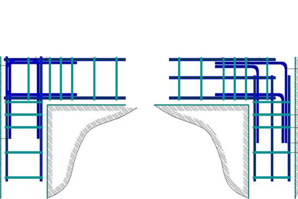 Twisting scheme
You will get 4 "blocks", which will be the length and width of one side minus 5 cm from all sides. Next, we will consider how to properly fasten them together and reinforce the corners on which most of the entire load falls.
Reinforcing the corners of the strip foundation
There is a multidirectional compressive force at the corners, since the soil has the properties to expand or narrow depending on the season, to sink under the influence of the large weight of the building, or to be washed away by groundwater. Errors when reinforcing corners should not be allowed, since it can turn out 4 different foundations who'll live their lives. Cracks and breaks will be difficult to avoid and such a design will be as inefficient as foundations without reinforcement. There are several ways to strengthen corners.
- Special welded mesh. used finished construction to strengthen the lower and upper tiers of the foundation. Cell no more than 200 x 200 mm, the thickness of the reinforcement depends on the weight of the structure, most often - 12 mm. Every 50-60 cm, the tiers of the metal mesh are connected by vertical reinforcement. Bypass at corners - from 80 centimeters.
- Reinforcement of the strip foundation with separate reinforcing bars. It is generally accepted that this is The best way, since it is not desirable to allow welded joints in the reinforcement belt. It can be divided conditionally into several categories:
- reinforcement with L-shaped longitudinal reinforcement of corners with bypass legs from 60 centimeters;
- reinforcement with U-shaped elements of right angles and junctions;
- strengthening of adjunctions with L-shaped products.
Below are a few examples of how NOT to reinforce corners.
 No Gain Small Overlap
There are several important rules reinforcing the corners of strip foundations, which must be adhered to:
- the length of the bypasses must be at least 50 diameters of the reinforcement used;
- when strengthening wide angles (more than 160 0), the reinforcement must repeat its outline and be intact;
- at a value less than 160 0 only external reinforcement can be intact;
- the step of the transverse jumpers must be equal to at least 0.75 of the height of the foundation and not more than 50 centimeters;
- anchoring of reinforcement in concrete is carried out: by the direct end of the rod, paws, hooks, bending of the rod (loop). It is not desirable to use welded joints and cementing.
Below are several correct options for reinforcing corners according to SNiP (tape type foundations)

 wide angle

 Overlap reinforcement
  Correct scheme
Reinforcement may not be the easiest job for a beginner builder, but a few hours of time spent will save a huge amount of money that would have been spent on hiring a professional team and a lot of related costs.
The foundation is the foundation of any building, which is erected in the first place and takes on not only the load of the entire structure, but also the load from the soil during seasonal heaving, excessive precipitation and temperature changes. In this case, the main compressive load is assumed by the concrete component, and the tensile load is assumed by the steel reinforcement. And therefore, in order to improve the solidity of the building, a technology called "reinforcement of the strip foundation" is used.
It is the strip foundation that is most often used in the construction of buildings made of logs, glued beams, cinder blocks or bricks with a small number of storeys (usually 2-3 floors). The tape-type base has the appearance of a closed contour, precisely distributed along the perimeter of the building in accordance with the plan of the house. That is, such a foundation is mounted under each of bearing walls buildings where the goal is to evenly distribute the load from the house to the ground.
Important: incorrectly executed reinforcement of the strip foundation can soon lead to the destruction of not only the entire contour, but also the built building. That is why the reinforcement of the building foundation requires a careful and balanced approach, as well as compliance with the technologies regulated by SNiP.
Reinforcement technology
Reinforcement of the strip foundation is carried out at the initial stages of construction, namely, before pouring the concrete solution into the formwork. To strengthen the contour of the foundation, steel elements are used, which are assembled into a lattice structure with specified parameters. In this case, the calculation of the parameters of the reinforcing crate is carried out taking into account the height, length and width of the base tape.
The reinforcing grid is erected at the stage of formwork installation, after which it is poured with concrete in layers using a construction vibrator. Such a device allows you to better expel air bubbles from the structure of the solution and make it more dense and strong after drying. Lastly, waterproofing of the reinforced base is performed using special mastic and roofing material.
Types of rod for reliable reinforcement

In order for the reinforcement of the strip foundation by reinforcement to be reliable, it is necessary to use high-quality steel elements of a certain class. So, professionals suggest using a rod marked for longitudinal reinforcement class A-I II (today - A400) with a herringbone surface or simply with a ribbed top. The diameter of such steel should be from 10 to 22 mm, depending on the width and height of the base. Such frame elements will be the basis for the entire frame. That is why they are stacked in the amount of four pieces on each side of the foundation tape, two from the bottom and two from the top, creating a frame with the help of short longitudinal corner rods.
For transverse and vertical reinforcement, steel of a smaller section of class A-I (today A240) is most often used, which have a smooth surface. The diameter of such elements is from 4 to 10 mm, since the load on them is not as colossal as on rods for longitudinal laying.
Important: the spacing of the transverse and vertical angles during the installation of the crate varies from 30 to 50 cm, depending on the width and length of the base tape. At the same time, the upper longitudinal elements of the crate should not go deeper into the solution by more than 5 cm. Otherwise, the benefit of reinforcing the foundation from the bearing walls will be minimal.
Calculation of the amount of reinforcement
You can also use our online calculator calculation of reinforcement strip foundation.
To carry out high-quality reinforcement at the stage of material procurement, it is necessary to calculate its quantity. In order to understand how many rods will be needed to complete installation work, you can use the reinforcement weight factor used by professionals for many years.
Important: for reinforcing the foundation tape for low-rise houses (private construction), for many years it was withdrawn and accepted as building code weight of reinforcement required for arranging 1m3 of foundation. This value is 80 kg.
Thus, in order to calculate the required weight of reinforcement for a particular foundation, it remains to calculate the amount of concrete consumed for the construction of the foundation. To do this, it is enough to know the perimeter of the future house, the length of the bearing walls, the height and width of the foundation.
Example: with a concrete quantity of 20m3, the weight of the required reinforcement should be 1600 kg, that is, 20x80=1600.
- It is necessary to draw a general reinforcement scheme and calculate the number of linear meters of the rod required to equip the entire crate, knowing all the parameters of the foundation. To the result you need to add another 5-10%, which may be used for trimming.
- Now it is necessary to find out the weight per linear meter of the steel frame elements of the longitudinal and transverse / vertical arrangement.
- It remains to multiply the linear meters obtained when drawing the scheme by the weight of the rods for a specific purpose.
Important: if you do it yourself correct calculation do not undertake, it is better to entrust this stage of work to professionals.
Assembly of the crate

At the stage of installation of the reinforcing lattice, it is necessary to go through the stage of knitting steel rods into a single structure. To do this, use a steel wire with a cross section of 2 mm.
Important: welding during the installation of a reinforcing lattice is completely prohibited, since steel loses its strength characteristics during the welding process, which means that the erected house will not be reliable. Welding is allowed by SNiP only if steel marked C is used for the frame. For example, A500C steel bar. This letter indicates that the material is suitable for welding.
Reinforcement is knitted using a special construction hook, which facilitates the formation of steel loops.
Reinforcement is knitted as follows:
- A piece about 30 cm long is cut from a common coil of wire;
- It is folded in half and applied to two rods that will be connected;
- Now the hook is threaded into the existing loop of wire and one free end is captured, passed into the loop and bent around the steel element;
- The second end of the wire is wrapped around the second rod in the same way through a loop, fastening them together at an angle of 90 degrees.
Thus, all structural elements are knitted.
Important: you can also use a special nozzle for a screwdriver or electric hooks to assemble the frame.
The distance of the rods in the crate according to SNiP

In SNiP 52-01-2003, the indentation from one element of the reinforcing frame to another is clearly regulated, thanks to which both professionals and private craftsmen can comply with the strip foundation technology.
So, the rules of SNiP are as follows:
- The minimum distance of the transverse steel bars from each other in the reinforcing crate depends entirely on the diameter of the elements, the size of the aggregate fractions for concrete, the location of the frame elements in relation to the direction of pouring the mortar and the method of laying the walls, but not less than 25 cm.
- The distance between the longitudinal elements of the frame is calculated taking into account the type of future structure (the presence of bay windows, balconies, columns, etc.), the height and width of the foundation tape. But at the same time, the distance between the longitudinal rods must either correspond to half of its height, or be from 30 to 50 cm.
Corner reinforcement technology

An important element in the construction of a steel bar crate is the reinforcement of the corners of the foundation. A big mistake is to assemble the structure from separate rods at an angle of 90 degrees. Even a securely connected structure in this case does not give any guarantee of the reliability of the foundation, since the frame elements in this case do not represent a reliable rigid frame and can be compressed and stretched. As a result, cracks and chips will appear at the corners of the foundation, which will subsequently lead to the destruction of the house.
Important: when reinforcing corners, only bent rods are used, which are then knitted with longitudinally located elements at a distance of 50-70 cm from the very corner of the foundation.
Reinforcement of bay windows and ledges

Often, for the beauty of the future building, the project provides for ledges under the veranda or the so-called bay window. A foundation is also poured under it, associated with a tape one.
In this case, it is also necessary to use the technology of bending the rod in the form of an obtuse angle.
The reinforcement technology will look like this:
- The bent steel is placed on the ledge of the foundation, and its edges lead to the outer longitudinal elements;
- Now the internal rods of the longitudinal arrangement are passed through the bent frame and connected together;
- Then the outer longitudinal frame elements are also bent after their junction with the curved element and brought to the inner ones;
- And to strengthen the structure, rods bent in the form of G and a sufficient number of clamps are used.
Several rules for high-quality reinforcement

In order to prevent a possible violation of the structure of the foundation and the subsequent destruction of the building, when reinforcing, it is also necessary to adhere to certain rules prescribed in SNiP:
- When installing a steel crate for reinforcement, it is necessary to avoid possible contact of the steel bar with the ground or formwork. This can subsequently lead to corrosion of the metal and a decrease in its technological characteristics. Therefore, it is very important to reliably deepen all frame elements into concrete. On all sides, steel should be buried in concrete by no more than 50-80 mm.
- To reinforce the corners of the foundation, you can use both L-shaped bent rods and U-shaped ones. In both cases, the structural elements are connected to the longitudinal ones using clamps.
Mankind has accumulated vast experience in construction throughout its existence. The basis, the base of any building is a solid and reliable foundation. Today, the most common type of foundation is the one that allows the foundation, because it is this construct that evenly distributes the weight of buildings on the ground, which in turn affects the shrinkage process of the house. And the reinforcement of the strip foundation is a way to make the foundation of the structure stronger and more reliable.
Steel and concrete are the main load-bearing Construction Materials. The properties of materials differ from each other. Comparative table of properties of some materials:
As you can see, steel is much stronger and more reliable than concrete, but at the same time, concrete is 80 times cheaper than steel. Therefore, a composite material reinforced concrete appeared. Since concrete works well in compression, the location of steel in iron concrete structures- in places subject to stretching and bending.
Many believe that the foundation only works to compress and reinforce the strip foundation - money thrown to the wind. This is correct if the foundation is placed on rocky soils. But in most cases, the soil is not a solid monolith. There are many factors that make a bending base work:
- Soil heterogeneity. Different density of layers leads to uneven shrinkage.
- Erosion of soil by atmospheric precipitation or groundwater.
- Mobility of the surface layers of the soil.
- Frosty swelling. Proximity ground water and negative temperature causes clay soils to increase in size by 10-15% (swell). In this case, the base begins to squeeze the foundation up.
As a result, stress arises in concrete structures, destroying the material. Cracks and shrinkage of the foundation lead to the formation of cracks in the walls of the house, which spoils appearance building or its collapse. In other words, saving on reinforcing the foundation is more expensive for yourself, because repairing and restoring a house requires tangible cash costs.

Reinforcement technology is a process of creating a spatial reinforcement cage. It consists of the following elements:
- longitudinal reinforcement;
- transverse;
- vertical;
- reinforcing clamps;
- knitting wire.
Longitudinal reinforcement is laid along the long side of the foundation, and the length of the rod usually reaches 6 or 12 m. It is she who resists stretching. Longitudinal reinforcement is performed along the top and bottom edges reinforced concrete structure.

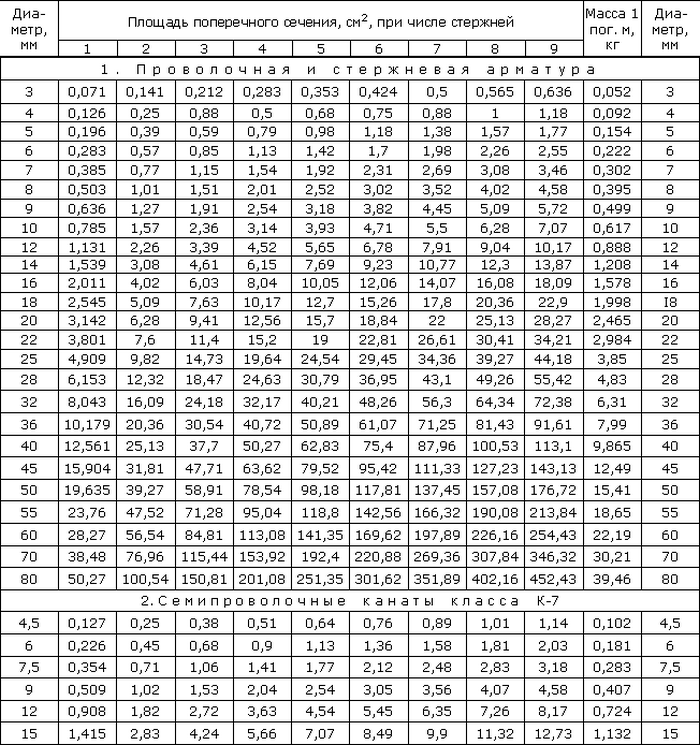
The laying pattern depends on the calculation of the required cross-sectional area of the reinforcement. Such a calculation requires careful consideration of all loads on the foundation, including climatic ones from snow and wind, as well as the own weight of the foundation. The bearing capacity of the soil is taken into account according to geological studies (geological section). In GOST 5781-82, table 1 contains the cross-sectional area for each rod diameter, it remains to decide how many rods to place on the upper and lower sides of the foundation.
However, for those who decide to build a house on their own, with their own hands, you can do without calculations, using the recommendations of clause 10 and section 5 of the Manual "On the design of concrete and reinforced concrete structures made of heavy concrete without prestressing reinforcement." They indicate that the minimum cross-sectional area of \u200b\u200bthe reinforcement is As \u003d µ * b * ho, where:
As is the cross-sectional area of the reinforcement;
µ= 0.1% - percentage for bending structures;
b is the width of the section of the strip foundation;
ho - height working area section (equal to half the height of the section of the foundation).

The diameter of the upper rods can be equal to the diameter of the lower ones or taken smaller. The maximum distance between the axes of the longitudinal rods (step) is recommended to be taken no more than 1.5h or no more than 400 mm in beams and slabs, where h> 150 mm is the height of the foundation cross-section (clause 10.3.8 of the joint venture and clause 5.13 of the Handbook). Only in this case, the effective operation of concrete and reinforcement is ensured, and the width of the crack opening between the longitudinal bars is limited.
The minimum spacing of the rods (distance between axes) is limited for reasons of ease of installation and compaction concrete mix and equals:
- d + 25 mm - for the lower reinforcement row;
- d + 30 mm - for the top.
Consider an example:
It is necessary to reinforce the strip foundation 400 mm wide, 600 mm high. You need to calculate how many rods you need and choose the diameter. The minimum cross-sectional area of the reinforcement is: As \u003d 40x30x0.1% \u003d 1.2 cm². The distance between the rods is 1.5x600 = 900 mm, therefore, we will take no more than 400 mm. That is, 2 rods are installed along the width of the section. We select the diameter of the reinforcement according to GOST 5781-82 table 1: two rods Ø 8 mm have an area As \u003d 2x0.503 \u003d 1.006 cm², which is less than the required 1.2 cm². Consider the following diameter Ø 10 mm. As \u003d 2x0.785 \u003d 1.57 cm². As a result, the layout of the rods looks like this: take the upper and lower reinforcement equal to Ø 10 mm and lay them in two rows.
Many builders today use the following rules to select the diameter of the rods: the diameter must be at least 10 mm if the side of the foundation is less than or equal to 3 m, and 12 mm for a side more than 3 m (see the Manual "Reinforcement of elements of monolithic reinforced concrete buildings" Appendix 1). However, the rules of the manual are designed for the design of monolithic reinforced concrete structures. multi-storey buildings taking into account emergency loads and progressive collapse. Of course, for those who build a house with their own hands, the margin of safety will not hurt, but we are no longer talking about a reasonable consumption of reinforcement.

When installing reinforcement, one should not forget about the protective concrete layer - the distance between the side surface of the strip foundation and the reinforcement bar. The protective layer is necessary for several reasons: it protects the steel from the aggressive effects of air and groundwater. In addition, for the normal operation of reinforced concrete, the reinforcement must be inside the concrete. The minimum layer size depends on the operating conditions of the structure and for structures located in soils, foundations with a concrete preparation device, it is 40 mm and not less than the diameter of the working reinforcement (Table 10.1 of the SP and Table 5.1 of the Manual).
Read more about the calculation of reinforcement.
Transverse structural reinforcement
Structural transverse reinforcement means horizontal and vertical bars, which:
- Support longitudinal reinforcement in the design working position.
- Prevent the development of cracks.
- Perceive an unaccounted load, for example, lateral buckling of the foundation.
The diameter of the transverse reinforcement in knitted flexible frames is assumed to be at least 6 mm. In Appendix 1 of the Manual "Reinforcement of elements of monolithic reinforced concrete buildings", transverse reinforcement is recommended to be performed in the form of a closed clamp with a rod diameter of at least 8 mm.

Device for bending reinforcement clamps.
The distance between the rods (step) is taken no more than twice the width of the cross section and not less than 600 mm. As for the protective layer, the minimum distance between the rod and the concrete edge is 5 mm less than the minimum layer size for longitudinal working reinforcement, i.e. 35 mm.
Materials used
Reinforcement materials are accepted in accordance with GOST 5781-82. The fittings are made of low-alloy and carbon steel in accordance with GOST 380-2015. The surface of the rods can be smooth or with a periodic profile. Depending on the properties, the material is divided into the following classes:
- A 240 (A-I);
- A 300 (A-II);
- A 400 (A-III);
- A 600 (A-IV);
- A 800 (A-V);
- A 1000 (A-VI).

For the foundation, reinforcement with a sickle-shaped profile is needed.
The numerical code reflects the yield strength, for example 240 corresponds to 235 N/mm². Among them, only A 240 (A-I) is made with a smooth profile. In the range of products are limited to a diameter of 6 to 40 mm.
Frames can be welded or bonded. For bonding and reinforcement, low-carbon steel wire GOST 6727-80 round is used ( grade B-I) or ribbed (grade Вр-I), diameter 3.0; 4.0.
Tip: The best solution for the foundation would be A400 (AIII) reinforcement, the use of higher grades is not justified, because. without prestressing, its strength potential will not be used 100%.
I would like to note that in last years fiberglass composite reinforcement appeared in the construction industry. The material is durable and lightweight. The material has many advantages: easy installation technology, has high anti-corrosion properties.

Photo of composite reinforcement.
However, the material also has disadvantages. It has self-extinguishing characteristics during combustion, but at a temperature of 200 ° C it loses its properties. In addition, it does not bend well, which makes it difficult to use bent elements. Many professional builders refused to work with this material due to the lack of practical experience (foreign experience was not taken into account) and calculation recommendations.
But since July 2015, Appendix L has appeared in SP 63.13330.2012 with rules for the design and calculation of structures. For those who prefer to build with their own hands, there are design requirements for reinforcement.
Rules for reinforcing corners and junctions
Often at the construction site, reinforcement has to be made from remnants, so the rods are overlapped, welded, or special butt joints are used. When overlapping, the ends of the smooth profile reinforcement are bent in the form of paws, hooks and loops, and the ends with a periodic profile can not be bent. The distance between joined bars can be from zero to 4 reinforcement diameters. The length of the joint is calculated according to the design manual, but cannot be less than 15 bar diameters or 200 mm.


Butt welded joints are performed using clips, and in mechanical joints, threaded and crimp couplings are used.
Important! The rules prohibit reinforcing corners with a simple overlap, since in this case the corner will not be integral and motionless.
Angular and T-shaped junctions of frames are made in three ways: with paws, with additional curved clamps of L and U shapes.

Photo how to properly reinforce the corner.
Learn more about corner reinforcement.
Knitting armature
It would seem that welded frames are faster and more convenient to use. However, builders prefer to knit space frames. And there are reasons for this:
- Welding reduces the quality of the metal.
- Soil settlement during the production of foundations provokes additional stresses at the joints. Welding joints do not always cope with loads and are destroyed. Connected parts do not change position in space, but have a certain mobility.
Advice! If you need contractors, there is a very convenient service for their selection. Just send in the form below detailed description work that needs to be done and offers with prices from construction teams and firms will come to your mail. You can see reviews of each of them and photos with examples of work. It's FREE and there's no obligation.
The corners and junctions of the strip foundation are places of concentration of multidirectional stresses. Incorrect docking of the longitudinal working reinforcement at the junctions and at the corners can lead to the appearance of transverse cracks, delaminations and spalls in these problem areas. Proper reinforcement of the strip foundation ensures the resistance of the reinforced concrete structure to the forces of compression and tension in all its sections.
Fig.1. Loads on the corner of the foundation.
The general rules for the use of reinforcement in the construction of strip foundations are set out in. Clause 8.9 of this document states that the foundations of the walls must be combined into a system of cross tapes and have a rigid bond between them. The methods of rigid connection of reinforcement are described in. Clause 8.3.26 lists all acceptable ways of such connections:
1. Docking reinforcement without welding, overlap. The following anchoring methods are allowed in the overlap area: with straight ends of corrugated reinforcement, with welding of transverse rods, with bends at the ends in the form of hooks or loops.
2. Welding of fittings.
3. The use of mechanical devices, or threaded couplings.
The rigidity of the reinforcement connection at the corners or junctions can only be ensured by these methods. Connections by knitting crosshairs when reinforcing the corners of the strip foundation are not allowed. In this case, an angular rupture of the reinforcing cage occurs and its integrity is lost. To reinforce the corner reinforcing joints, U- and L-shaped elements made of reinforcing bars used for the installation of longitudinal (working) reinforcement can be used. Vertical and transverse clamps in the area of corner and adjacent anchorages are installed 2 times more often than in other parts of the strip foundation. The optimal distance between the clamps in the areas of junctions and corners is determined as half of ¾ of the height of the tape. It is not recommended to make this distance more than 25 cm. To evenly distribute the loads at the corners of the tape, as well as in the area of \u200b\u200bjunctions, a rigid bundle of internal and external longitudinal reinforcement is made.
Reinforcement schemes for corners and junctions
To form a single rigid spatial frame of a strip foundation, the following schemes of corner and adjacent joints of longitudinal reinforcement are used:
1. Rigid corner connection of reinforcement with an overlap and a "foot".
2. Reinforcement of the corner zone with an L-shaped clamp.
3. Scheme of reinforcing the corner using a U-shaped clamp.
4. Reinforcement of the junction area with overlap joints.
Fig. 5. Scheme of reinforcement of the adjacent zone using an L-shaped clamp.
6. Reinforcement of the junction area with a U-shaped clamp.
7. Reinforcement of obtuse corners with a rigid overlap joint.
Any of the above correct schemes provides for a rigid connection of the internal and external longitudinal reinforcement.
Reinforcement of the corner area with rigid lap joints and "paws"
1. The rigidity of the gusset of the external horizontal reinforcement is provided with an overlap by bending one of the free ends (1-2).
2. Binding of the inner horizontal reinforcement (7) to the outer horizontal reinforcement (2) is carried out with an overlap.
3. Binding of the internal horizontal reinforcement (3) to the external bundle (1-2) is made using the "foot" connection.
4. The step of the corner transverse reinforcement (5) and vertical reinforcement (4) is calculated by the formula 3/8 of the height of the strip foundation.
5. The length of the "foot" is 35-50 diameters of the longitudinal reinforcement.
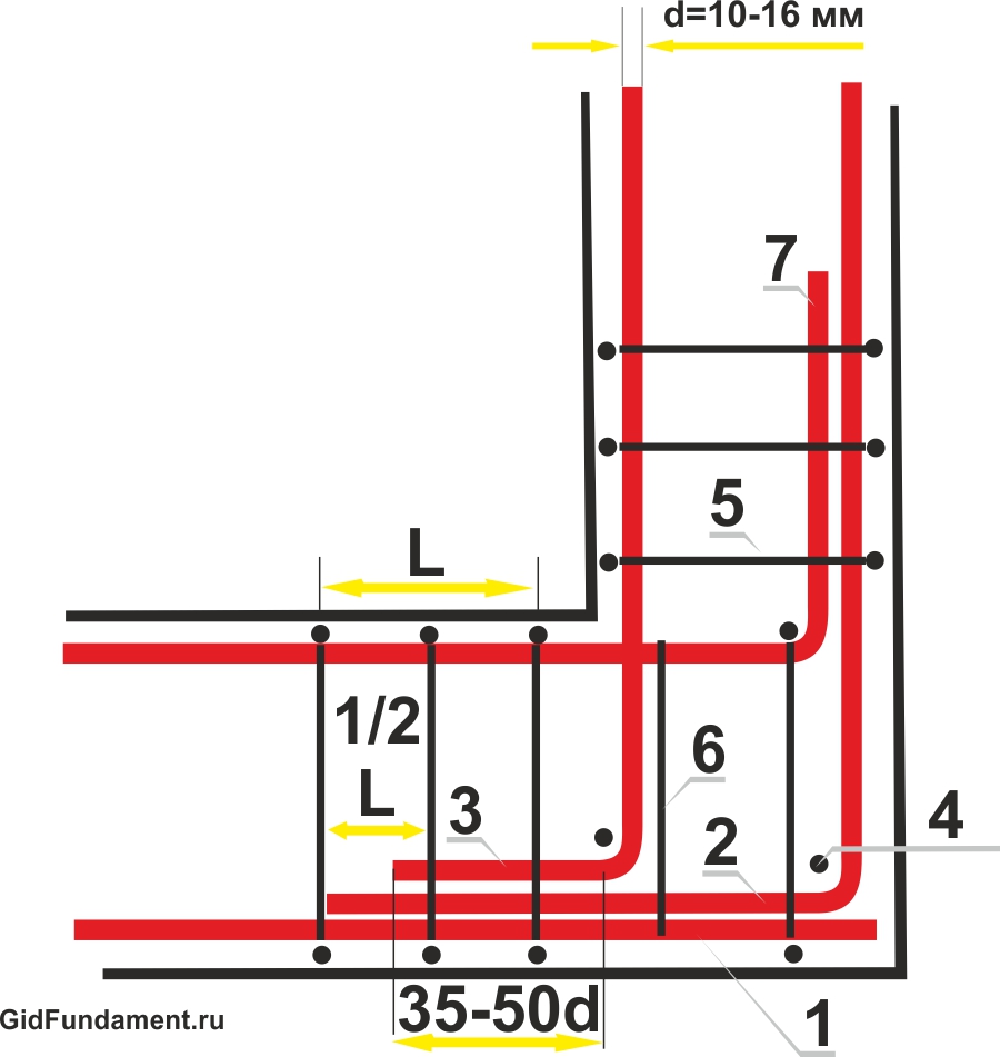
Rice. 2. Scheme of reinforcing the corner of the strip foundation with an overlap.
Reinforcement of the corner zone of the strip foundation using an L-shaped clamp
1. The rigidity of the connection of the external longitudinal reinforcement (1) in the corner zone is provided by the L-shaped clamp (6).
2. The inner longitudinal reinforcement (2) is rigidly fastened to the outer longitudinal reinforcement (1) with an overlap.
3. The step of the transverse reinforcement (L) is no more than ¾ of the height of the foundation tape.
4. An additional transverse reinforcement (5) connects the inner and outer longitudinal reinforcement.
5. The length of the lap joint is 50 horizontal reinforcement diameters.
Rice. 3. Scheme of reinforcing the corner of the strip foundation with an L-shaped clamp.
Reinforcing the corner of the strip foundation with a U-shaped clamp
1. When using U-shaped clamps (5), the corner connection of the external and internal horizontal reinforcement of the strip foundation (1) receives a rigid hitch like a lock.
2. Vertical (2), transverse (3) and additional transverse (4) reinforcement are involved in the anchoring of U-shaped clamps.

Rice. 4. Scheme of reinforcing the corners of the strip foundation with a U-shaped clamp.
Reinforcement of the junction area with overlap joints
1. The connection of the horizontal reinforcement (2) of the adjacent element of the strip foundation with an overlap is carried out only to the external horizontal reinforcement (1).
2. The step of the transverse (4), additional transverse (5) and vertical reinforcement in the junction area must be at least 3/8 of the height of the foundation tape.
3. The dimensions of the lap joint are 50 diameters of the working reinforcement.

Fig.5. Scheme of reinforcement of the junction of the strip foundation with an overlap.
Reinforcement of the junction zone with an L-shaped clamp
1. When using an L-shaped clamp (6) to reinforce the abutment zone, the horizontal reinforcement of the adjoining part and the external horizontal reinforcement (1) are connected to the overlap angle.
2. The length of the lap joint (2) is 50 diameters of the working reinforcement.
3. The pitch of the vertical (3) and transverse reinforcement (4) in the junction area is halved with the help of additional transverse reinforcement (5).
Rice. 6. Scheme of reinforcement of the junction of the strip foundation with an L-shaped clamp.
The use of a U-shaped clamp for reinforcing the zone of junction of the strip foundation
1. A U-shaped clamp (6) provides additional rigid overlapping of the horizontal reinforcement of the adjacent element of the strip foundation (3) to the external horizontal reinforcement (1).
2. The length of the lap joint (2) can be 35-50 horizontal reinforcement diameters.
3. The minimum allowable length of the U-shaped clamp should be equal to twice the width of the strip foundation.

Rice. 7. Scheme of reinforcement of the junction of the strip foundation with an L-shaped clamp.
Overlapping reinforcement of blunt corner joints of a strip foundation
1. For reliable connection reinforcing cage when turning the strip foundation at an obtuse angle (1), a scheme of rigid overlapping of the free ends of the internal horizontal reinforcement (4) with the external horizontal reinforcement (5) is used.
2. Vertical (2) and horizontal (3) reinforcement in the overlapping area should be installed 2 times more often than on flat sections of the tape.
3. The length of the lap joint must be at least 50 diameters of the longitudinal reinforcement.
Rice. 8. Scheme of reinforcement of an obtuse corner of a strip foundation.
Typical mistakes when reinforcing corners and junctions
All the correct methods of corner and adjoining reinforcement joints used in the construction of a strip foundation are aimed at maintaining the integrity of the reinforcement cage, regardless of its configuration. The strength of the strip foundation depends on the correct anchoring of the end elements of the longitudinal reinforcement. The following schemes lead to incorrect reinforcement of the corners of the strip foundation:
1. Reinforcement of the corner zones of the strip foundation with reinforcing crosshairs with viscous rods of longitudinal reinforcement at right angles.
2. Installation in corner and adjacent areas of bent longitudinal reinforcement without anchoring.
These errors are the most common and can lead to the destruction of the foundation at corner joints and junctions.
Corner and adjoining joints made by knitting crosshairs of longitudinal reinforcement bars
1. The rods of the longitudinal reinforcement (1) directed at an angle to each other do not form a rigid coupling and cannot resist the tension that occurs due to loads in the middle part of the strip foundation.
2. Elements of transverse (3) and vertical reinforcement have only a constructive function.
A typical mistake in reinforcing corners and junctions is the connection of longitudinal reinforcement by the method of knitting crosshairs. Such a reinforcing connection without proper anchoring of the rods can lead to the destruction of the concrete monolith due to multidirectional loads that occur at the corners of the strip foundation.

Rice. 9. Common mistake when reinforcing corners
The use of bent longitudinal reinforcement for the reinforcement of corner joints and junctions
1. Corner joints without a bunch of internal and external longitudinal reinforcement (1) do not provide rigid rod fixation.
2. The destruction of the foundation can occur not only due to the formation of transverse cracks, but also due to peeling of internal corners.

Rice. 10. Another example of incorrect corner reinforcement
In order to prevent the formation of cracks, spalls and delaminations at the corners and junctions of the strip foundation, it is necessary to correctly connect the end rods of the longitudinal reinforcement and perform their reliable anchoring. Proper reinforcement of the corners of the strip foundation is the key to the reliability and durability of the building.
Advice! If you need contractors, there is a very convenient service for their selection. Just send in the form below a detailed description of the work to be done and you will receive offers with prices from construction teams and firms by mail. You can see reviews of each of them and photos with examples of work. It's FREE and there's no obligation.
- Reinforcement of a monolithic structure
- Reinforcement technology
- Stages of proper reinforcement of the strip foundation
- Frame for strip foundation
The foundation is the basis for the construction of each house, the most important part of any building. It goes to the foundation maximum load home in general. And then on to the ground.
Work is carried out according to the following principle:
- determination of the pressure force of the foundation;
- choice of type, dimensions, diameter, relief of reinforcement;
- a ditch breaks out corresponding to;
- reinforcement rods with a diameter of 8-10 mm are stuck into the ground, in strictly designated places, along the entire length of the base of the house, with an interval of 200 cm, corresponding to the height.
- horizontal rods are knitted vertically (a distance of 5 cm remains to the surface of the foundation). Reinforcement protrusions above the foundation surface are allowed, but they should not be higher than 10 cm.
Builders for reinforcement are advised to use brick fragments, this will help to install the reinforcing elements more evenly.