From the article you will learn how to make an adjustable power supply with your own hands from available materials. It can be used to power household equipment, as well as for the needs of your own laboratory. A constant voltage source can be used to test devices such as a relay regulator for a car generator. After all, when diagnosing it, there is a need for two voltages - 12 Volts and over 16. Now consider the design features of the power supply.
Transformer
If the device is not planned to be used to charge acid batteries and power powerful equipment, then there is no need to use large transformers. It is enough to use models with a power of no more than 50 W. True, to make an adjustable power supply with your own hands, you will need to slightly change the design of the converter. The first step is to decide what voltage range will be at the output. The characteristics of the power supply transformer depend on this parameter.
Let's say you chose the range of 0-20 Volts, which means you need to build on these values. The secondary winding should have an output voltage of 20-22 Volts. Therefore, you leave the primary winding on the transformer and wind the secondary winding on top of it. To calculate the required number of turns, measure the voltage that is obtained from ten. A tenth of this value is the voltage obtained from one turn. After the secondary winding is made, you need to assemble and tie the core.
Rectifier

Both assemblies and individual diodes can be used as a rectifier. Before making an adjustable power supply, select all its components. If the output is high, then you will need to use high-power semiconductors. It is advisable to install them on aluminum radiators. As for the circuit, preference should be given only to the bridge circuit, since it has a much higher efficiency, less voltage loss during rectification. It is not recommended to use a half-wave circuit, since it is ineffective; there is a lot of ripple at the output, which distorts the signal and is a source of interference for radio equipment .
Stabilization and adjustment block

To make a stabilizer, it makes the most sense to use the LM317 microassembly. A cheap and accessible device for everyone, which will allow you to assemble a high-quality do-it-yourself power supply in a matter of minutes. But its application requires one important detail - effective cooling. And not only passive in the form of radiators. The fact is that voltage regulation and stabilization occurs according to a very interesting scheme. The device leaves exactly the voltage that is needed, but the excess coming to its input is converted into heat. Therefore, without cooling, the microassembly is unlikely to work for a long time.
Take a look at the diagram, there is nothing super complicated in it. There are only three pins on the assembly, voltage is supplied to the third, voltage is removed from the second, and the first is needed to connect to the minus of the power supply. But here a small peculiarity arises - if you include a resistance between the minus and the first terminal of the assembly, then it becomes possible to adjust the voltage at the output. Moreover, a self-adjustable power supply can change the output voltage both smoothly and stepwise. But the first type of adjustment is the most convenient, so it is used more often. For implementation, it is necessary to include a variable resistance of 5 kOhm. In addition, a constant resistor with a resistance of about 500 Ohms must be installed between the first and second terminals of the assembly.
Current and voltage control unit
Of course, in order for the operation of the device to be as convenient as possible, it is necessary to monitor the output characteristics - voltage and current. A circuit of an regulated power supply is constructed in such a way that the ammeter is connected to the gap in the positive wire, and the voltmeter is connected between the outputs of the device. But the question is different - what type of measuring instruments to use? The simplest option is to install two LED displays, to which connect a volt- and ammeter circuit assembled on one microcontroller.

But in an adjustable power supply that you make yourself, you can mount a couple of cheap Chinese multimeters. Fortunately, they can be powered directly from the device. You can, of course, use dial indicators, only in this case you need to calibrate the scale for
Device case
It is best to make the case from light but durable metal. Aluminum would be the ideal option. As already mentioned, the regulated power supply circuit contains elements that get very hot. Therefore, a radiator must be mounted inside the case, which can be connected to one of the walls for greater efficiency. It is desirable to have forced airflow. For this purpose, you can use a thermal switch paired with a fan. They must be installed directly on the cooling radiator.
Somehow recently I came across a circuit on the Internet for a very simple power supply with the ability to adjust the voltage. The voltage could be adjusted from 1 Volt to 36 Volt, depending on the output voltage on the secondary winding of the transformer.
Take a close look at the LM317T in the circuit itself! The third leg (3) of the microcircuit is connected to capacitor C1, that is, the third leg is INPUT, and the second leg (2) is connected to capacitor C2 and a 200 Ohm resistor and is an OUTPUT.
Using a transformer, from a mains voltage of 220 Volts we get 25 Volts, no more. Less is possible, no more. Then we straighten the whole thing with a diode bridge and smooth out the ripples using capacitor C1. All this is described in detail in the article on how to obtain constant voltage from alternating voltage. And here is our most important trump card in the power supply - this is a highly stable voltage regulator chip LM317T. At the time of writing, the price of this chip was around 14 rubles. Even cheaper than a loaf of white bread.
Description of the chip
LM317T is a voltage regulator. If the transformer produces up to 27-28 volts on the secondary winding, then we can easily regulate the voltage from 1.2 to 37 volts, but I would not raise the bar to more than 25 volts at the transformer output.
The microcircuit can be executed in the TO-220 package:

or in D2 Pack housing

It can pass a maximum current of 1.5 Amps, which is enough to power your electronic gadgets without voltage drop. That is, we can output a voltage of 36 Volts with a current load of up to 1.5 Amps, and at the same time our microcircuit will still output 36 Volts - this, of course, is ideal. In reality, fractions of volts will drop, which is not very critical. With a large current in the load, it is more advisable to install this microcircuit on a radiator.
In order to assemble the circuit, we also need a variable resistor of 6.8 Kilo-Ohms, or even 10 Kilo-Ohms, as well as a constant resistor of 200 Ohms, preferably from 1 Watt. Well, we put a 100 µF capacitor at the output. Absolutely simple scheme!
Assembly in hardware
Previously, I had a very bad power supply with transistors. I thought, why not remake it? Here is the result ;-)
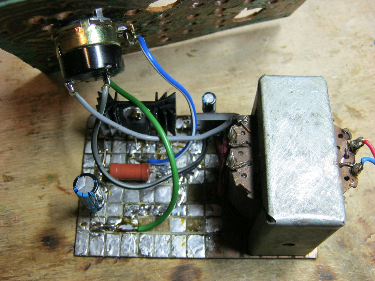
Here we see the imported GBU606 diode bridge. It is designed for a current of up to 6 Amps, which is more than enough for our power supply, since it will deliver a maximum of 1.5 Amps to the load. I installed the LM on the radiator using KPT-8 paste to improve heat transfer. Well, everything else, I think, is familiar to you.

And here is an antediluvian transformer that gives me a voltage of 12 volts on the secondary winding.

We carefully pack all this into the case and remove the wires.
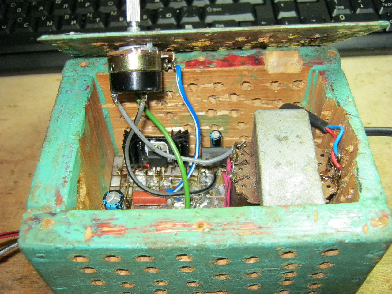
So what do you think? ;-)

The minimum voltage I got was 1.25 Volts, and the maximum was 15 Volts.

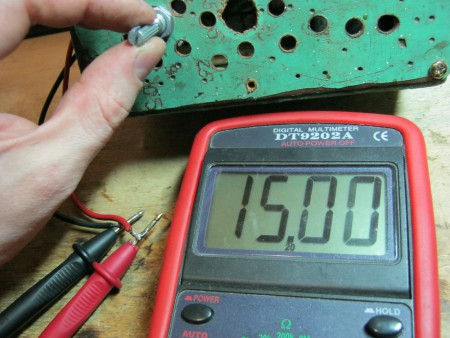
I set any voltage, in this case the most common are 12 Volts and 5 Volts
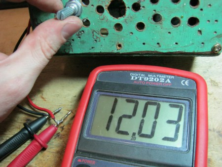

Everything works great!
This power supply is very convenient for adjusting the speed of a mini drill, which is used for drilling circuit boards.

Analogues on Aliexpress
By the way, on Ali you can immediately find a ready-made set of this block without a transformer.

Too lazy to collect? You can buy a ready-made 5 Amp for less than $2:

You can view it at this link.
If 5 Amps is not enough, then you can look at 8 Amps. It will be enough for even the most seasoned electronics engineer:

So the next device has been assembled, now the question arises: what to power it from? Batteries? Batteries? No! The power supply is what we will talk about.
Its circuit is very simple and reliable, it has short-circuit protection and smooth adjustment of the output voltage.
A rectifier is assembled on the diode bridge and capacitor C2, circuit C1 VD1 R3 is a reference voltage stabilizer, circuit R4 VT1 VT2 is a current amplifier for power transistor VT3, protection is assembled on transistor VT4 and R2, and resistor R1 is used for adjustment.
I took the transformer from an old charger from a screwdriver, at the output I got 16V 2A
As for the diode bridge (at least 3 amperes), I took it from an old ATX block as well as electrolytes, a zener diode, and resistors.
I used a 13V zener diode, but the Soviet D814D is also suitable.
The transistors were taken from an old Soviet TV; transistors VT2, VT3 can be replaced with one component, for example KT827.
Resistor R2 is a wirewound with a power of 7 Watts and R1 (variable) I took nichrome for adjustment without jumps, but in its absence you can use a regular one.
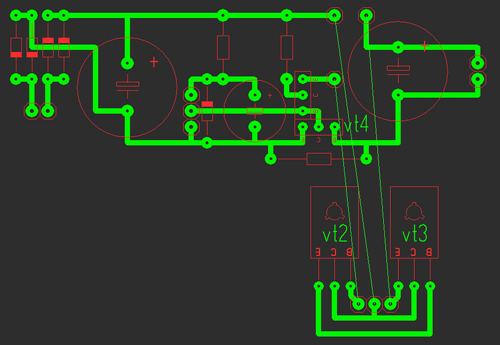
It consists of two parts: the first one contains the stabilizer and protection, and the second one contains the power part.
All parts are mounted on the main board (except for power transistors), transistors VT2, VT3 are soldered onto the second board, we attach them to the radiator using thermal paste, there is no need to insulate the housing (collectors). The circuit was repeated many times and does not need adjustment. Photos of two blocks are shown below with a large 2A radiator and a small 0.6A.

Indication
Voltmeter: for it we need a 10k resistor and a 4.7k variable resistor and I took an indicator m68501, but you can use another one. From resistors we will assemble a divider, a 10k resistor will prevent the head from burning out, and with a 4.7k resistor we will set the maximum deviation of the needle.
After the divider is assembled and the indication is working, you need to calibrate it; to do this, open the indicator and glue clean paper onto the old scale and cut it along the contour; it is most convenient to cut the paper with a blade.

When everything is glued and dry, we connect the multimeter in parallel to our indicator, and all this to the power supply, mark 0 and increase the voltage to volts, mark, etc.
Ammeter: for it we take a resistor of 0.27 ohm!!! and variable at 50k, The connection diagram is below, using a 50k resistor we will set the maximum deviation of the arrow.
The graduation is the same, only the connection changes, see below; a 12 V halogen light bulb is ideal as a load.
List of radioelements
| Designation | Type | Denomination | Quantity | Note | Shop | My notepad |
|---|---|---|---|---|---|---|
| VT1 | Bipolar transistor | KT315B | 1 | To notepad | ||
| VT2, VT4 | Bipolar transistor | KT815B | 2 | To notepad | ||
| VT3 | Bipolar transistor | KT805BM | 1 | To notepad | ||
| VD1 | Zener diode | D814D | 1 | To notepad | ||
| VDS1 | Diode bridge | 1 | To notepad | |||
| C1 | 100uF 25V | 1 | To notepad | |||
| C2, C4 | Electrolytic capacitor | 2200uF 25V | 2 | To notepad | ||
| R2 | Resistor | 0.45 Ohm | 1 | To notepad | ||
| R3 | Resistor | 1 kOhm | 1 | To notepad | ||
| R4 | Resistor |
Quite often, during testing, it is necessary to power various crafts or devices. And using batteries, selecting the appropriate voltage, was no longer a joy. Therefore, I decided to assemble an regulated power supply. Of the several options that came to mind, namely: converting a computer ATX power supply, or assembling a linear one, or purchasing a KIT kit, or assembling from ready-made modules - I chose the latter.
I liked this assembly option because of its undemanding knowledge of electronics, the speed of assembly, and, if something happens, the quick replacement or addition of any of the modules. The total cost of all components was about $15, and the power ended up being ~100 Watts, with a maximum output voltage of 23V.
To create this regulated power supply you will need:
- Switching power supply 24V 4A
- Buck converter for XL4015 4-38V to 1.25-36V 5A
- Volt-ampermeter 3 or 4 characters
- Two step-down converters on LM2596 3-40V to 1.3-35V
- Two 10K potentiometers and knobs for them
- Two banana terminals
- On/off button and 220V power connector
- 12V fan, in my case 80mm slim
- Any body you like
- Stands and bolts for mounting boards
- The wires I used were from a dead ATX power supply.


After finding and purchasing all the components, we proceed to assembly according to the diagram below. Using it, we will get an adjustable power supply with a voltage change from 1.25V to 23V and a current limit to 5A, plus the additional ability to charge devices via USB ports, the consumed amount of current, which will be displayed on the V-A meter.

We first mark and cut out holes for a volt-ampere meter, potentiometer knobs, terminals, and USB outputs on the front side of the case.

We use a piece of plastic as a platform for attaching modules. It will protect against unwanted short circuits to the housing.
We mark and drill the location of the board holes, and then screw in the racks.

We screw the plastic pad to the body.

We unsolder the terminal on the power supply, and solder three wires on + and -, the pre-cut length. One pair will go to the main converter, the second to the converter for powering the fan and volt-ampere meter, the third to the converter for USB outputs.

We install a 220V power connector and an on/off button. Solder the wires.

We screw the power supply and connect the 220V wires to the terminal.

We've sorted out the main power source, now let's move on to the main converter.
We solder the terminals and trimming resistors.

We solder the wires to the potentiometers responsible for regulating voltage and current, and to the converter.

We solder the thick red wire from the VA meter and the output plus from the main generator to the output positive terminal.

We are preparing a USB output. We connect the date + and - for each USB separately so that the connected device can be charged and not synchronized. Solder the wires to the paralleled + and - power contacts. It is better to take thicker wires.

Solder the yellow wire from the VA meter and the negative wire from the USB outputs to the negative output terminal.

We connect the power wires of the fan and the VA meter to the outputs of the additional converter. For the fan, you can assemble a thermostat (diagram below). You will need: a power MOSFET transistor (N channel) (I took it from the processor power harness on the motherboard), a 10 kOhm trimmer, an NTC temperature sensor with a resistance of 10 kOhm (thermistor) (I took it out of a broken ATX power supply). We attach the thermistor with hot glue to the main converter microcircuit, or to the radiator on this microcircuit. Using a trimmer, we set it to a certain temperature when the fan operates, for example, 40 degrees.


We solder the plus of the USB outputs to the output plus of another, additional converter.

We take one pair of wires from the power supply and solder it to the input of the main converter, then the second to the additional input. converter for USB to provide incoming voltage.

We screw the fan with the grille.

Solder the third pair of wires from the power supply to the extra. converter for fan and VA meter. We screw everything to the site.


We connect the wires to the output terminals.

We screw the potentiometers onto the front side of the housing.

We attach the USB outputs. For reliable fixation, a U-shaped fastening was made.

We adjust the output voltages to additional. converters: 5.3V, taking into account the voltage drop when connecting a load to USB, and 12V.


We tighten the wires for a neat internal appearance.

Close the housing with a lid.

We glue the legs for stability.

The regulated power supply is ready.


Video version of the review:
P.S. You can make your purchase a little cheaper using EPN cashback - a specialized system for returning part of the money spent on purchases from AliExpress, GearBest, Banggood, ASOS, Ozon. By using EPN cashback you can get back from 7% to 15% of the money spent in these stores. Well, if you want to make money on purchases, then this is the place for you -
When doing something regularly, people strive to make their work easier by creating various devices and devices. This fully applies to the radio business. When assembling electronic devices, one of the important issues remains the issue of power supply. Therefore, one of the first devices that a novice radio amateur often assembles is this.
Important characteristics of the power supply are its power, stabilization of the output voltage, and the absence of ripple, which can manifest itself, for example, when assembling and powering an amplifier, from this power supply in the form of background or hum. And finally, it is important for us that the power supply is universal so that it can be used to power many devices. And for this it is necessary that it can produce different output voltages.

A partial solution to the problem may be a Chinese adapter with switching the output voltage. But such a power supply does not have the ability to be smoothly adjusted and does not have voltage stabilization. In other words, the voltage at its output “jumps” depending on the supply voltage of 220 volts, which often sags in the evenings, especially if you live in a private house. Also, the voltage at the output of the power supply unit (PSU) may decrease when a more powerful load is connected. The power supply proposed in this article, with stabilization and regulation of the output voltage, does not have all these shortcomings. By rotating the variable resistor knob, we can set any voltage in the range from 0 to 10.3 volts, with the possibility of smooth adjustment. We set the voltage at the output of the power supply according to the readings of the multimeter in voltmeter mode, direct current (DCV).

This can come in handy more than once, for example, when testing LEDs, which, as you know, do not like being supplied with a voltage that is too high compared to the rated voltage. As a result, their service life can be sharply reduced, and in particularly severe cases, the LED can burn out immediately. Below is a diagram of this power supply:

The design of this RBP is standard and has not undergone significant changes since the 70s of the last century. The first versions of the circuits were using germanium transistors, later versions were using a modern element base. This power supply is capable of delivering power up to 800 - 900 milliamps, provided there is a transformer that provides the required power.

The limitation in the circuit is the diode bridge used, which allows currents of a maximum of 1 ampere. If you need to increase the power of this power supply, you need to take a more powerful transformer, a diode bridge and increase the radiator area, or if the dimensions of the case do not allow this, you can use active cooling (cooler). Below is a list of parts required for assembly:

This power supply uses the domestic high-power transistor KT805AM. In the photo below you can see its appearance. The adjacent figure shows its pinout:

This transistor will need to be attached to the radiator. In the case of attaching the radiator to the metal body of the power supply, for example, as I did, you will need to place a mica gasket between the radiator and the metal plate of the transistor, to which the radiator should be adjacent. To improve heat transfer from the transistor to the heatsink, you need to apply thermal paste. In principle, any one used for application to a PC processor will do, for example the same KPT-8.

The transformer should produce a voltage of 13 volts on the secondary winding, but in principle a voltage within 12-14 volts is acceptable. The power supply contains a filtering electrolytic capacitor with a capacity of 2200 microfarads (more is possible, less is not advisable), for a voltage of 25 volts. You can take a capacitor designed for a higher voltage, but remember that such capacitors are usually larger in size. The figure below shows a printed circuit board for the sprint-layout program, which can be downloaded in the general archive, attached archive.

I assembled the power supply not exactly using this board, since I had a transformer with a diode bridge and a filter capacitor on a separate board, but this does not change the essence.

A variable resistor and a powerful transistor, in my version, are connected by hanging mounting, on wires. The contacts of the variable resistor R2 are marked on the board, R2.1 - R2.3, R2.1 is the left contact of the variable resistor, the rest are counted from it. If, after all, the left and right contacts of the potentiometer were confused during connection, and the adjustment is carried out not from the left - minimum, to the right - maximum, you need to swap the wires going to the extreme terminals of the variable resistor. The circuit provides a power-on indication on the LED. Switching on and off is carried out using a toggle switch, by switching the 220 volt power supply supplied to the primary winding of the transformer. This is what the power supply looked like at the assembly stage:

Power is supplied to the power supply through the computer's native ATX power supply connector, using a standard detachable cable. This solution allows you to avoid the tangle of wires that often appears on a radio amateur’s desk.

The voltage at the output of the power supply is removed from laboratory clamps, under which any wire can be clamped. You can also connect standard multimeter probes with crocodiles at the ends to these clamps, by inserting them on top, for more convenient supply of voltage to the assembled circuit.

Although, if you want to save money, you can limit yourself to simple wiring at the ends with alligator clips, clamped using laboratory clamps. If using a metal housing, place a suitable size casing on the clamp securing screw to prevent the clamp from shorting to the housing. I have been using this type of power supply for at least 6 years now, and it has proven the feasibility of its assembly and ease of use in the daily practice of a radio amateur. Happy assembly everyone! Especially for the site " Electronic circuits"AKV.